 |
|
GSICS Wiki>Development web>AtbdCentral>AtbdMainFooBar (29 Oct 2009, AleksandarJelenak)


AtbdMainFooBar Title

...Text...
1. Find Collocations
A set of observations from a pair of instruments within a common period (e.g. 1 day) is required as input to the algorithm. The first step is to obtain these data from both instruments, select the relevant comparable portions and identify the pixels that are spatially collocated, temporally concurrent, geometrically aligned and spectrally compatible and calculate the mean and variance of these radiances.
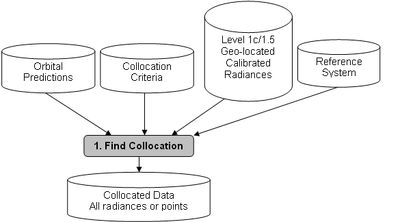 Figure2: Step 1 of Generic Data Flow, showing inputs and outputs
1.1. Select Orbit
...ATBD Step 1 Process 1 text...
1.1.1. Purpose
 Hide Option v0.1
Option v0.1 Title
We first perform a rough cut to reduce the data volume and only include relevant portions of the dataset (channels, area, time, viewing geometry). The purpose is to select portions of data collected by the two instruments that are likely to produce collocations. This is desirable because typically less then 0.1% of measurements are collocated. The processing time is reduced substantially by excluding measurements unlikely to produce collocations.Data is selected on a per-orbit or per-image basis. To do this, we need to know how often to do inter-calibration – which is based on the observed rate of change and must be defined iteratively with the results of the inter-calibration process (see 4.f).
Option v0.2 Title
...Option v0.2 text...Option v0.3 Title
...Option v0.3 text...Option v0.4 Title
...Option v0.4 text... 1.1.2. General Options
Hide Option v0.1
Option v0.1 Title
The simplest, but inefficient approach is “trial-and-error”, i.e., compare the time and location of all pairs of files within a given time window.Option v0.2 Title
A more sophisticated option is to use the observed orbital parameters (such as the Two Line Elements or TLE) with orbit prediction software such as Simplified General Perturbations Satellite Orbit Model 4 (SGP4). For instrument that has fixed or stable scan pattern such that the measurement time and location are determined by the satellite locations, this is very effective.Option v0.3 Title
...Option v0.3 text...Option v0.4 Title
...Option v0.4 text... 1.1.3. ATBD Step 1 Process 1 Level 3 Class IReeGL Title
Class IReeGL
Hide Option v0.1
Option v0.1 Title
For inter-calibrations between geostationary and sun-synchronous satellites, the orbits provide collocations near the GEO Sub-Satellite Point (SSP) within fixed time windows every day and night. In this case, we adopt the simple approach outlined in general option v0.1. We define the GEO Field of Regard (FoR) as an area close to the GEO Sub-Satellite Point (SSP), which is viewed by the GEO sensor with a zenith angle less than a threshold. Wu [2009] defined a threshold angular distance from nadir of less than Figure 3: Computing arc angle to satellite nadir and zenith angle of satellite from Earth location
Option v0.2 Title
...Option v0.2 text...Option v0.3 Title
...Option v0.3 text...Option v0.4 Title
...Option v0.4 text... 1.1.4. ATBD Step 1 Process 1 Level 4 Class IReeGL Instruments FooBar Title
Class IReeGL Instruments FooBar
Hide Option v0.1
Option v0.1 Title
...Option v0.1 text...Option v0.2 Title
...Option v0.2 text...Option v0.3 Title
...Option v0.3 text...Option v0.4 Title
...Option v0.4 text...Edit | Attach | Print version | History: r1 | View wiki text | Edit wiki text | More topic actions
Topic revision: r1 - 29 Oct 2009, AleksandarJelenak
- Useful wiki links:
-
 Attach multiple files to current topic
-
 User wiki documentation
-
 Quick editing reference
-
 Good style tips
-
 Installed wiki extensions
-
 Member-only web
-
 Test Wiki
- Tag cloud:
(Clicking a tag finds all topics tagged with it.)
A Test Topic ATBD convention equations error assessment examples FAQ file naming GPPA GSICS Correction GSICS Monitoring Imager ISO 19115 JAMI Joint WG meeting LaTeX Logo Lunar Workshop meetings metadata microwave Moon MTSAT netCDF products solar channel SubGroup traceability users Web meeting workflow workshop workshops
Ideas, requests, problems regarding GSICS Wiki? Send feedback